
Table of Contents
Cable tray seismic bracing helps keep a cable support route controlled when a building moves during an earthquake. The practical goal is not simply to add more steel. It is to provide a documented load path from the tray and its supports into the building structure, while preserving cable bend limits, access, and normal thermal movement. This guide explains what engineers, contractors, and buyers should confirm before hardware is selected.
What cable tray seismic bracing does
A normal trapeze or wall support carries gravity load. Cable tray seismic bracing is added to resist horizontal movement and, where the design requires it, vertical movement. A complete arrangement usually combines transverse restraints, longitudinal restraints, anchors, strut or other structural members, and connections to the tray support. Each part has to transfer force without relying on ceiling grid, ductwork, piping, or another nonstructural system.
A cable tray seismic bracing assembly should be treated as a complete system. A strong diagonal member does little if its anchor, fitting, support frame, or attachment point is not suitable for the calculated demand. Likewise, an excessively rigid detail can interfere with expansion joints or create concentrated stress at a tray splice.

When cable tray seismic bracing may be required
Requirements depend on the adopted building code, project specification, seismic design category, component importance, installation height, weight, and local authority. Cable tray seismic bracing should therefore be confirmed by the project structural or seismic design professional. Do not infer an exemption from tray width alone or copy spacing from an unrelated project.
For U.S. projects, teams commonly coordinate nonstructural component design with the locally adopted building code and the referenced edition of ASCE 7. The FEMA E-74 nonstructural guidance is also a useful planning reference. These sources do not replace project calculations or local approval.
Design inputs to collect before selection
Before requesting cable tray seismic bracing hardware, assemble the information that controls the design. At minimum, document the tray type and material, loaded weight per unit length, support spacing, elevation, route geometry, attachment substrate, anchor restrictions, and the governing seismic criteria. Include cable additions that are reasonably expected within the approved fill plan.
- Tray width, side-rail height, material, finish, and joint locations
- Maximum operating weight of tray, cables, covers, and accessories
- Support type, span, rod length, and connection geometry
- Concrete, structural steel, or engineered wood attachment conditions
- Clearance from ducts, pipes, ceilings, walls, and equipment
- Expansion joints, building separation joints, and flexible connections
- Required calculations, submittals, inspections, and approval sequence
Typical cable tray seismic bracing components
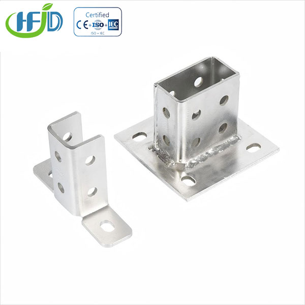
Most cable tray seismic bracing assemblies use readily coordinated structural parts, but their capacity must be checked as a connected system. Slotted channel can provide an adjustable brace or frame; browse the P1000T slotted strut channel for a representative support member. Connections may include channel fittings, beam clamps, base plates, and approved anchors. The exact combination depends on load direction and substrate.
| Component | Primary function | Key check |
|---|---|---|
| Transverse brace | Limits side-to-side movement | Angle, compression/tension capacity, connection clearance |
| Longitudinal brace | Limits movement along the route | Force transfer through supports and tray joints |
| Anchor or beam attachment | Transfers demand to structure | Substrate, edge distance, installation method, approved capacity |
| Strut fitting or bracket | Connects brace members | Bolt size, orientation, slip, and member compatibility |
| Flexible connection | Accommodates differential movement | Location at equipment or building joints |
How to plan the bracing layout
Begin with the support drawing rather than placing symbols on an electrical route plan in isolation. Cable tray seismic bracing locations should align with supports capable of receiving the brace force. Mark route ends, changes in direction, vertical offsets, equipment connections, and building joints. These conditions can change how longitudinal force travels through the installation.
Next, coordinate each cable tray seismic bracing angle and attachment point in three dimensions. A brace that looks clear in plan may collide with ductwork above the tray or block access to a cover. Keep access for cable pulling and future maintenance. Where wall support is appropriate, a purpose-built cable tray wall bracket may form part of the gravity support arrangement, subject to engineering review.
Coordination and installation details
Good cable tray seismic bracing drawings identify more than spacing. They show brace direction, member size, fitting orientation, anchor type, substrate, fastener details, and any required stiffening of long hanger rods. Details should also distinguish seismic restraints from ordinary sway control, because the design basis and documentation may differ.
During cable tray seismic bracing installation, keep braces straight and avoid field modifications that reduce section capacity. Do not drill structural steel, substitute anchors, or change brace angles without approval. Tightening procedures should follow the hardware and project requirements. After cables are installed, confirm that added weight and field routing remain consistent with the approved design.
Cable tray seismic bracing inspection checklist
- Verify installed locations and directions against approved drawings.
- Confirm that every brace connects to the designated building structure.
- Check anchors, edge distances, embedment indicators, and required inspection records.
- Confirm nuts, bolts, clamps, and fittings are present and correctly oriented.
- Look for bent strut, enlarged holes, cut threads, loose hardware, or unapproved welds.
- Check clearance through the expected movement zone.
- Verify that building joints and equipment connections remain flexible where specified.
- Record deviations and obtain design approval before concealment.
Cable tray seismic bracing inspection is most effective before ceilings close and before cable loading makes connections difficult to see. Photograph concealed attachments where project procedures allow. A traceable record also helps maintenance teams understand which members are structural restraints and should not be moved.
Common specification mistakes
The most common mistake is treating cable tray seismic bracing as a generic accessory quantity. The required hardware is tied to calculated demand and site geometry. Other frequent problems include attaching to ceiling components, ignoring tray joint capacity, using a brace angle outside the approved range, blocking cable access, and omitting coordination at building separation joints.
Procurement documents should separate verified project requirements from supplier options. Ask for material and finish compatibility, dimensional drawings, connection details, and traceable product identification. For adjustable support hardware, review compatible strut channel brackets as part of the assembly, then have the final configuration checked by the responsible design professional.
FAQ
Is every cable tray required to have seismic bracing?
No universal answer applies. Cable tray seismic bracing requirements depend on the governing code, exemptions, component weight, seismic criteria, importance, and local approval. Confirm the requirement for each project.
Can threaded rods provide seismic restraint?
Vertical hanger rods are normally part of the gravity support. They should not be assumed to resist horizontal seismic demand unless the engineered detail explicitly assigns and verifies that function.
Can one brace restrain several nearby services?
Only an engineered shared support designed for all applicable loads should do so. Independent systems should not be connected informally because their movement, weight, and approval requirements can differ.
Should braces be installed at expansion joints?
Building and tray expansion joints need coordinated movement details. Cable tray seismic bracing should not unintentionally lock a joint that must move; the engineer should define restraints and flexible sections on each side.
What should be sent with a hardware inquiry?
Send tray dimensions and material, loaded weight, support drawings, substrate information, brace directions, finish, quantities, and the approved design criteria. Clear inputs reduce unsuitable substitutions and speed technical review.
Prepare a coordinated hardware request
Cable tray seismic bracing is most reliable when load calculations, structural attachments, tray supports, and installation access are coordinated before ordering. PowerCableTray can review drawings and help identify compatible tray support and strut components for a defined project arrangement. Include the design criteria and connection details in your inquiry so the hardware discussion begins with the right constraints.