
جدول المحتويات
An airport cable tray can carry power, lighting, communications, security, baggage-handling, building controls, fire alarm, and other systems through a facility that operates continuously. The tray design must support circuit separation, fire strategy, future changes, structural loads, public-area coordination, and maintenance without disrupting critical airport functions.
Quick answer
Plan an airport cable tray by dividing the facility into terminal, baggage, utility, plant, parking, apron-support, and restricted operational zones. Build a cable schedule for each route, separate incompatible systems, choose tray construction from cable duty, and verify material, load, supports, fire stopping, bonding, and access. Provide realistic spare capacity, but do not leave empty space without a documented circuit and load plan.
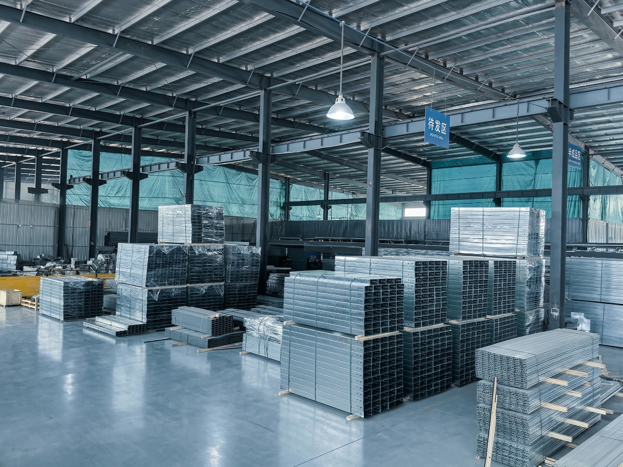
Map operational and environmental zones
A terminal ceiling, baggage tunnel, loading dock, electrical room, rooftop, passenger boarding bridge, and maintenance area create different risks. For each airport cable tray route, record temperature, humidity, water exposure, cleaning, outdoor weather, corrosion, vibration, impact, security restrictions, and permitted maintenance windows.
Coordinate the airport cable tray route with architecture and airport operations before supports are fixed. Airport cable tray routes in public ceilings require careful visual and access planning; back-of-house areas may be dense with ducts and pipes; baggage systems need equipment-removal space. The FAA Airport Terminal Planning advisory circular treats electrical and technology infrastructure as core terminal systems, reinforcing the need for early multidisciplinary coordination.
Group circuits by function and criticality
An airport cable tray schedule should identify normal power, emergency power, lighting, fire alarm, public address, access control, video, data, building automation, baggage controls, and other airport-specific systems. Record cable type, size, weight, bend radius, shielding, source, destination, and any route-diversity requirement.
Airport cable tray projects should use separate trays or approved dividers when electrical rules, system criticality, electromagnetic compatibility, or owner standards require them. The site’s cable tray separation guide explains practical routing options. Do not allow circuit groups to mix at bends, tees, panel entries, or penetrations after they have been separated on straight runs.
Choose tray construction around cable duty
| Tray type | Useful application | Design checks |
|---|---|---|
| Ladder | Large power cables and open service routes | Rung spacing, cleats, span, cable support |
| مثقوب | Control, communications, and smaller cables | Fill, ventilation, drainage, bend support |
| Wire mesh | Flexible routing and visible low-voltage runs | Load, supports, edge treatment, cable restraint |
| Solid-bottom | Selected routes needing added shielding | Heat, water retention, covers, inspection |
A ladder airport cable tray can support larger feeder routes, while perforated or wire-mesh systems often suit controls and communications. Solid-bottom tray may protect selected cables from debris, but it can limit ventilation and hide contamination. Choose fittings and covers with the straight sections so bend radius, drainage, and circuit separation remain consistent.
For high-load power routes, review the صينية كابل سلم مجلفنة للخدمة الشاقة against actual cable loads and spans. Product selection must follow the project electrical design; tray type alone does not establish cable ampacity, fire performance, or system availability.
Select materials for the actual environment
Indoor conditioned areas, humid baggage spaces, coastal terminals, rooftops, and chemical storage rooms may need different airport cable tray materials. Compare galvanized steel, stainless steel, aluminum, coated steel, and nonmetallic systems using corrosion exposure, temperature, UV, cleaning agents, mechanical loads, fire requirements, and maintenance capability.
Airport cable tray specifications should include fittings, brackets, bolts, clamps, covers, and bonding parts as part of the same system. Dissimilar metals can create localized corrosion where moisture is present. For outdoor or exposed routes, include wind effects on covers and allow drainage rather than creating closed pockets.

Plan loads, supports, and movement
Calculate airport cable tray load from installed cables, fittings, covers, dividers, accessories, and stated future additions. Support spacing must use verified manufacturer data for the selected tray, orientation, and load. The IEC 61537:2023 standard specifies requirements and tests for cable tray and cable ladder systems, including safe working load procedures.
Airport cable tray supports require coordinated anchors with the structural design and avoid attaching to unrelated services. Long routes and building joints may require movement provisions. Where vibration is expected near baggage equipment or mechanical plant, verify fasteners, restraints, and inspection intervals. Keep supports out of access doors, lifting paths, and equipment maintenance zones.
Installation and handover checks
- Confirm route, elevation, system identification, and security-zone requirements.
- Verify anchors, brackets, spans, couplers, and fitting supports.
- Maintain cable bend radius, fill, separation, and restraint.
- Remove sharp edges and repair damaged finishes with approved methods.
- Complete bonding and grounding according to the electrical design.
- Coordinate penetrations with the approved fire-stopping system.
- Record field changes and photograph concealed sections.
Before energization, inspect the entire airport cable tray route for loose hardware, deformation, unsupported fittings, blocked access, cable jacket damage, unsealed penetrations, and unapproved circuit mixing. For routes associated with emergency or life-safety functions, verify the complete cable-support construction against the project’s documented fire strategy.
A colored coating or product name does not prove circuit-survival performance. Where a protected system is being considered, review the fire-resistant cable tray configuration, then request evidence matching the required cable, supports, installation orientation, and duration.
Design for changes and maintenance access
Airport systems change frequently as tenants, security equipment, passenger processing, retail, and technology evolve. Keep airport cable tray routes visible, labeled, and reachable so additions can be reviewed before installation. Do not treat nominal empty area as available capacity without checking load, fill, heat, separation, and support conditions.
Airport cable tray routine inspection should look for corrosion, loose supports, damaged covers, cable movement, unauthorized additions, and blocked access. Coordinate work windows with airport operations. Update drawings and cable schedules whenever routes or circuit groups change, especially where redundant systems depend on physical route diversity.
الأسئلة الشائعة
Which tray type is best for airport terminals?
No single type fits every terminal. Choose ladder, perforated, wire mesh, or solid-bottom tray from cable duty, load, access, environment, and fire strategy.
Can power and data cables share a tray?
Only when applicable rules, cable ratings, EMC design, and owner standards permit it. Separate trays or approved dividers are often used.
Does every airport cable tray need a cover?
No. Covers should address a defined hazard and must be checked for heat, drainage, attachment, access, and wind where exposed.
How is support spacing determined?
Use actual cable and accessory loads, tray orientation, fittings, structural conditions, and verified manufacturer load data.
What belongs in a supplier inquiry?
Provide route drawings, cable schedules, dimensions, loads, spans, fittings, materials, covers, fire requirements, environment, and applicable standards.
Prepare a coordinated airport specification
A reliable airport cable tray design connects cable classification, operational zones, fire strategy, structural supports, material exposure, installation access, and future changes. Send the cable schedule and route conditions with the inquiry so the tray, fittings, supports, and accessories can be reviewed as one system.